 MCP for Blender
Real2Sim: turning a robot recording into a simulation with MCP for Blender
Many robots learn tasks from recordings of a robot doing them. Trekion gave Claude one of those recordings, a robot arm moving a mug, and had it rebuild the room in Blender so the task can be practised and tested without the robot. Through MCP for Blender, Claude built the scene in six and a half minutes and checked it against all three real cameras.
Built by Trekion
Trekion rebuilds real sites as photoreal, physics-accurate simulations for training and testing robots.
Rebuild your own episodes
The prompts below work for any recorded episode that has calibrated cameras and a joint log.
Generate environments in Blender with Premium
Get access to the best 3D generation models like Meshy, Tripo and Hyper3D Rodin.
Trekion builds simulation infrastructure for physical AI. It rebuilds real sites as photoreal, physics-accurate environments, so robotics teams can train and evaluate robots before deploying them.
Why rebuild a recording in simulation
Many robots learn tasks by imitation. A person guides the robot through a task, like picking up a mug and moving it, and each attempt is recorded. That recording is called an episode: video from every camera, where each camera sits, and the robot's joint angles at every step. The model that controls the robot, its policy, is trained on thousands of them.
Real episodes are slow to collect, and each one shows a single room, layout and lighting. Testing a policy means running the real robot, one trial at a time. In a simulation of the same scene, you can run a policy as often as you like without the robot, and move the mug, change the lights or swap objects to make new training data.
Rebuilding a real scene as a simulation that matches it is called real2sim. It only works if the simulation looks like the real cameras and behaves like the real objects. Otherwise, what the policy learns in simulation doesn't carry over to the robot. By hand, someone has to model every room and object and line each one up with the real cameras.
Trekion wanted to see whether an AI agent could build these scenes from the recording. Trekion wrote the prompts, and Claude wrote and ran all the Blender code through MCP for Blender.
Most examples here use one episode from the public DROID dataset, about 76,000 robot episodes recorded in 564 scenes. In this one, a Franka robot arm moves a green mug across a white table, filmed by two fixed cameras and a camera on its wrist.
- 6.5 min
- for Claude to rebuild the scene
- ~30
- tool calls, of the 80 budgeted
- 3
- real cameras it checked its work through
- 0.92
- best per-camera SSIM, from a 76-minute run
From real episode to simulation and back
The pipeline has seven steps. Steps 1 to 3 happen in Blender. From step 4, a robotics simulator handles the physics, with Claude running it from the terminal, and Blender still renders the images.
| Step | Where | What comes out |
|---|---|---|
| 1. Prepare | Terminal, MCP for Blender | Cameras in Blender terms, the robot posed at step 0, a calibration check |
| 2. Rebuild | MCP for Blender | The room, table and objects, matched through all three cameras |
| 3. Refine | MCP for Blender | Scores per camera and object, fixed one mismatch at a time |
| 4. Sim-ready | MCP for Blender, simulator | Colliders, mass and friction, exported as USD or MJCF |
| 5. Calibrate | Isaac Sim or MuJoCo | Physics fitted to the real motion, checked on another episode |
| 6. Vary | MCP for Blender, simulator | Visual variations and new demonstrations |
| 7. Back to the robot | The real robot | A test of whether the synthetic data helps |
What you need
From the episode: one undistorted frame from each camera plus the video, each camera's intrinsics (fx, fy, cx, cy) and pose in the robot base frame, and the joint log with the gripper state and the control rate (15 Hz for DROID). You also need a robot model, as a URDF or MJCF with meshes. MuJoCo Menagerie has many arms and grippers.
For software, you need Blender 4.2 or newer with the MCP for Blender add-on running, and an agent that can use MCP and has a terminal and Python. Trekion used Claude Code. The physics steps need Isaac Sim, Isaac Lab or MuJoCo.
Claude uses four groups of MCP for Blender tools here:
| Tool | What Claude uses it for |
|---|---|
execute_blender_code | Running Python in the live Blender session: cameras, geometry, materials, lights, renders |
look | Seeing the scene, including through each real camera |
get_scene_info | Listing what's in the scene and where |
search_assets, import_asset, generate_3d | Bringing in objects from asset libraries, or generating them |
Step 1: Get the cameras and the robot right first
Claude can build almost everything from images, except two things: exact camera poses and the robot's pose. Images can't pin those down reliably, so Trekion had Claude prepare them first and check them before building anything else.
Prepare the inputs for rebuilding step 0 of this robot episode in Blender.
Files: <calibration file>, <joint log>, <robot model>, <frame from each camera>.

1) Convert every camera into Blender terms (metres, Z up, robot base at the origin): focal length, lens shift from the principal point, and the camera pose converted from the OpenCV convention (looks along +Z, Y down) to Blender's (looks along -Z, Y up). Write them to cameras.txt with one block per camera.
2) Pose the robot at step 0 by forward kinematics from the logged joint angles and gripper value, and export it as robot_step0.glb.
3) Check the calibration: in Blender, create the cameras from cameras.txt, import the robot and render each camera with the robot over the real frame. Report how well the robot silhouette lines up in each view. If a camera is clearly off, re-estimate its pose from the robot silhouette and say how far it moved from the recorded pose.
Don't skip the check in part 3. Recorded calibration is sometimes wrong. If a camera is off, every object Claude places through it will be off too, and the mismatch will look like a modelling problem.
Step 2: Rebuild the scene through the real cameras
This is the prompt for the rebuild. In the run in the video, Claude finished in six and a half minutes.
Rebuild this real robot scene in Blender from scratch. It is step 0 of a recorded episode: <one line describing the robot, the table and the objects on it>.
Inputs (absolute paths):
- ext1.jpg, ext2.jpg, wrist.jpg: photos from the two fixed cameras and the wrist camera (1280x720)
- cameras.txt: all three cameras, ready for Blender (metres, Z up, robot base at the origin)
- robot_step0.glb: the robot, already posed for this frame from its joint log

1) Create cameras named ext1, ext2 and wrist exactly from cameras.txt and import the robot. Check that the robot lines up in all three photos: it is your ruler.
2) Model the room and the table at metric scale, then the objects on the table with matching materials. Place each object so it lines up in all three views, not just one. Use SAM to identify all the objects in the scene, build each object individually with Hunyuan3D or SAM 3D, and place them according to the metric depth.
3) Add lighting to match the photos.
4) After each major step, render the cameras, compare the renders with the photos and fix the biggest mismatch.
Budget: about 80 tool calls. Finally save scene.blend and render ext1.png, ext2.png and wrist.png at 1280x720.
What each instruction does:
- Give it the cameras and the robot poseThose are the two things it can't recover from images.
- "It is your ruler"The robot's size is known exactly, so Claude can use it to get metric scale. With stereo cameras, depth from the pair works too.
- "Lines up in all three views"Depth is ambiguous from one camera. This stops Claude fitting an object to one view and missing it in the others.
- "Fix the biggest mismatch"Each round gets one target instead of endless polishing.
- A tool-call budgetIt caps the run at about 80 calls. This one used about 30.
Behind the scenes of the six-minute run
For the recording, Trekion locked three Blender viewports to ext1, ext2 and wrist, with the real photo as a faint overlay so viewers could see the match form. The prompt told Claude to compare against its renders, not the viewports. The overlay was only for people watching.
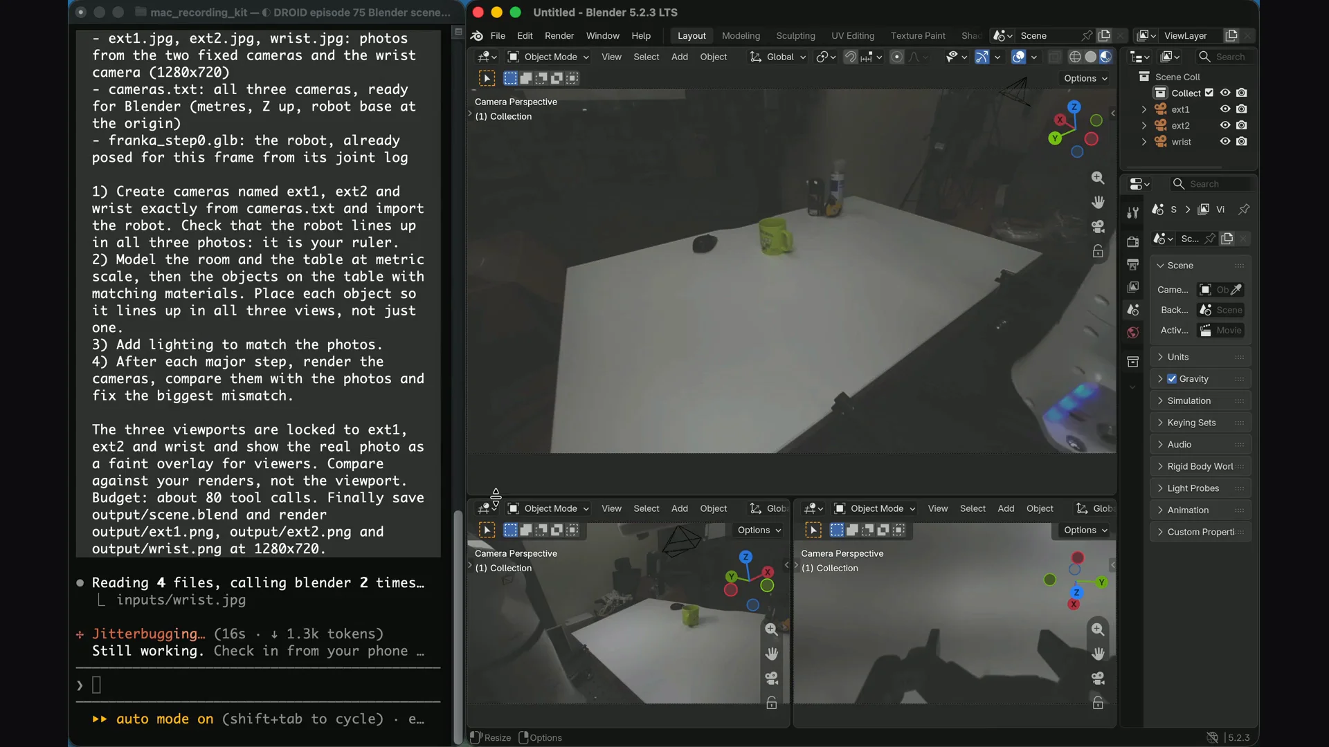
Claude set up the cameras and imported the robot, then triangulated where each object sat from the two fixed cameras. After that it followed the loop: render, compare, fix the biggest mismatch. Its status lines show what it found each round:
- "Cameras are set up and the robot imported; now triangulating object positions from the two fixed photos."
- "Fixing the overlapping breadboard and overexposure, then re-rendering."
- "Renders are brighter than the photos everywhere; dimming walls/glass and lights, then re-measuring."
- "Alignment is good in all three views. Saving the .blend and rendering the final 1280x720 outputs."
To match the lighting, Claude sampled the same regions in the photos and in its renders and compared their brightness. The near table came out at 0.84 against 0.82 in the photo, and the walls and glass within about 0.1.
Its final report also listed what it hadn't matched. The wrist image is darker than the fixed cameras (0.53 against 0.82 on the left of the table), because the wrist camera exposes differently and one lighting setup can't match all three, so Claude tuned for the fixed cameras. The office behind the glass was simplified. The objects were basic shapes, with no print on the mug and only a blue band for the can labels. It used about 30 tool calls of the 80 budgeted.
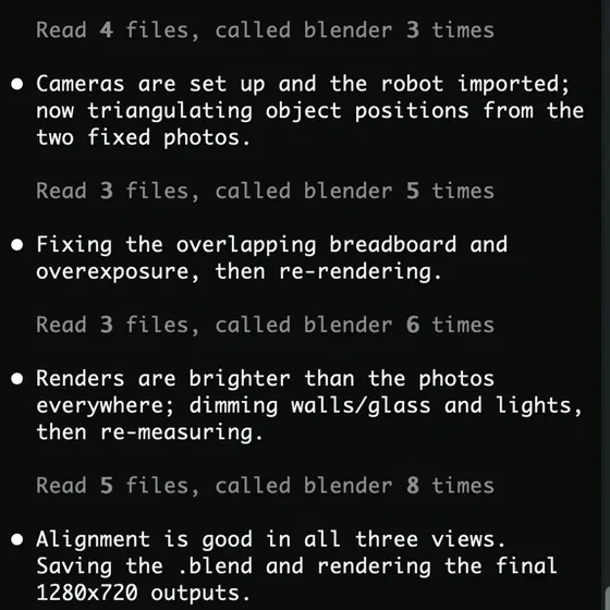 During the run · one target per round
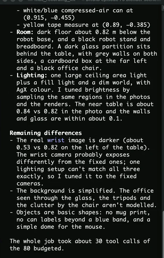 The report · including what it didn't match
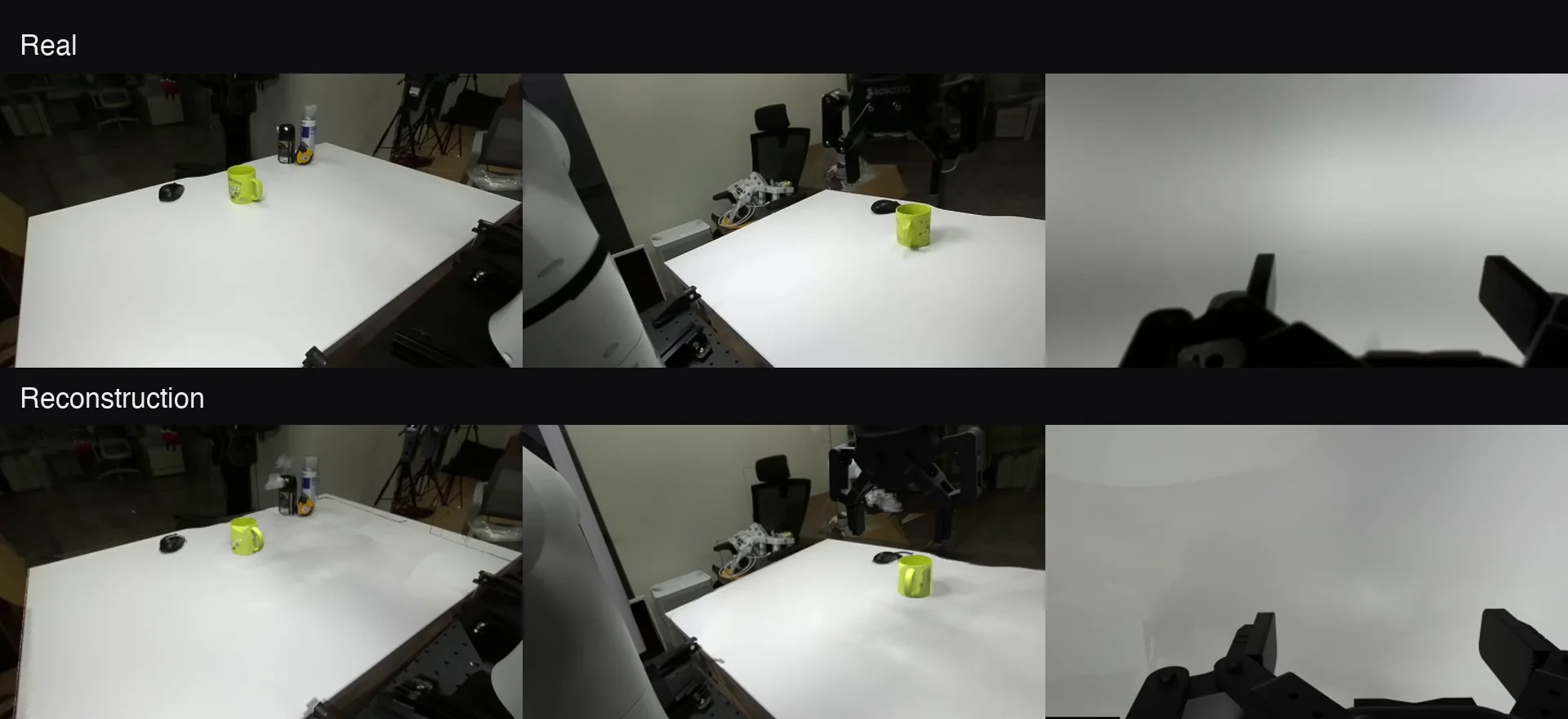
Step 3: Push the match further
The first build gets the layout right. Fidelity comes from more rounds of the same loop, with numbers to steer by. Trekion used follow-ups like these:
Score the match: compute grayscale SSIM between each render and its photo, and the mask overlap (IoU) for the table, the robot and each object. List the three worst mismatches.
Fix the worst mismatch, re-render all three cameras and re-score. Repeat until no camera improves by more than 0.01, then stop and report the final scores.
A scene can match step 0 and still be wrong where the robot moves. So the last check uses frames Claude hasn't seen:
Check the scene on frames you haven't seen: render the cameras at steps 40, 80 and 120 with the robot posed from the joint log, and compare them with the real frames at those steps.
More time buys more fidelity. The six-and-a-half-minute run placed the table and objects correctly but left the office behind the glass unmodelled. It scored an SSIM (a 0 to 1 measure of how alike two images look) of 0.66 to 0.80 per camera. A 76-minute run of the same loop on another episode reached 0.90 to 0.92.
Step 4: Make the scene sim-ready
A Blender scene only covers how things look. A simulator also needs a collision shape, a mass and a friction value for everything the robot touches.
Make this scene ready for <Isaac Sim | MuJoCo>.
1) For every object the robot touches, create a simplified collision shape: a box for the table, convex hulls for small objects, and a convex decomposition for concave ones like the mug. Keep each collider within a few millimetres of the visual mesh, and report the largest gap.
2) Give each movable object a mass and friction value. Label each value as measured or estimated, and give the source of every estimate.
3) Export the scene as <USD with physics schemas (rigid body, collision, mass) | MJCF that includes the robot>, load it in the simulator, and check that every object rests stably on the table for 5 seconds without the robot moving.
Labelling each value as measured or estimated pays off in step 5. When the simulated mug doesn't move like the real one, you know which numbers to distrust first.
Blender's rigid-body solver is fine for quick placement checks. Run robot contact in a robotics simulator.
Step 5: Fit the physics to the real motion
Images give you appearance, not mass or friction. To make objects move the way they did in reality, the physics has to be fitted against the recorded motion.
Track the mug through the episode in all three camera videos, and confirm that video frame k is control step k. Then, in <simulator>, replay the episode's logged commands through a controller that matches the real robot's (same control mode and rate). Compare the simulated mug path with the tracked path, and fit only the parameters that matter for this task: mug mass, mug-table friction and gripper pad friction. Report:
- the final mug position error before and after fitting;
- how much each parameter actually changes the result.
Flag any parameter the episode can't pin down.
Validate the fitted values on a different episode with the same object, without refitting. Report the mug path error there.
In the mug episode, sweeping the mug's mass and friction moved its final position by under 2 mm. One episode couldn't tell which values were right.
- Calibrate on several interactionsDifferent pushes, or several episodes with the same object.
- Ask how much each parameter changes the resultIf a value barely moves the outcome, as with the mug, the fit can't pin it down.
- Trust only held-out resultsA replay can look perfect on the trajectory it was fitted to.
Step 6: Multiply the scene into variations
Once one scene matches the real recording, each variation is a small edit to a scene Claude already built, and Claude can check it by rendering the three cameras again.
Visual variations are for training images and robustness tests:
Create 10 variations of this scene. For each one:
- change the mug colour and material roughness;
- move the mug and the other objects to random non-overlapping spots on the table, within 15 cm of where they started;
- scale the key light by 0.6–1.4 and rotate the environment lighting;
- jitter each fixed camera by up to 1 cm and 2 degrees.
Keep the robot and the calibration unchanged. Render all three cameras for each variation, plus object masks and depth. Save every variation's parameters to a JSON file next to its images.
Trajectory variations are new demonstrations. They need the calibrated physics from step 5:
Using the calibrated scene in <simulator>, generate 10 new demonstrations of the same task:
1) Randomize the mug's start pose on the table within 15 cm and 45 degrees.
2) Adapt the real trajectory to each new start pose, keeping the grasp relative to the mug.
3) Run each one in the simulator and keep only the runs where the mug ends at the target.
4) For the successful runs, render all three cameras in Blender from the simulated robot and object poses.
5) Report the success rate and save each demonstration with its parameters.
What to vary depends on what you want the policy to handle:
| Axis | Examples | Mainly for |
|---|---|---|
| Object identity | Different mugs, distractors from search_assets or generate_3d | Generalizing to new objects |
| Appearance | Colours, materials, textures | Visual robustness |
| Lighting | Energy, colour temperature, direction | Visual robustness |
| Camera | Pose jitter, exposure | Calibration robustness |
| Layout | Start poses, clutter | Spatial generalization (needs new trajectories) |
| Physics | Mass and friction within the fitted ranges | Dynamics robustness |
For training data, randomize broadly. For evaluation, keep the variations realistic and tied to what the real deployment will see.
Step 7: Back to the real robot
Only a real robot can show whether any of this helps. Taking what was learned in simulation back to the robot closes the loop, which is why the whole pipeline is often called real2sim2real. Claude can set up the comparison:
Set up the comparison for the real-robot test:
1) Train one policy on the real demonstrations only, and one on the same real demonstrations plus the synthetic ones.
2) Write the protocol for testing both on the real robot: same start poses for both, at least 20 trials each, and success criteria defined before testing.
3) Prepare the matching simulated test, so we can check whether simulation ranks the two policies the same way the real robot does.
Until a real-robot test agrees, treat results from the simulation as a hypothesis.
Try it yourself
Pick an episode from DROID or your own recordings, and start with step 1. To get set up, install MCP for Blender and connect it to Claude. The robotics docs cover exporting scenes for simulators.